
Passe Passe Layer 2 FPGA Network Switch Verilog
Having a FPGA that can send and receive Ethernet packets and generate custom IP/UDP packets can be the cornerstone of many large designs. But what if you have multiple Ethernet ports or want to avoid having an additional piece of hardware that does your layer 2 network routing? The solution is to have a flexible all in one solution that lives all on the FPGA fabric itself and can provide layer 2 routing, packet parsing, and packet generation that is configurable for any number of physical Ethernet ports. Below we will discuss the details and workings of a design that enables such functionality. All system verilog code and test benches for the design can be found here.
Design Overview
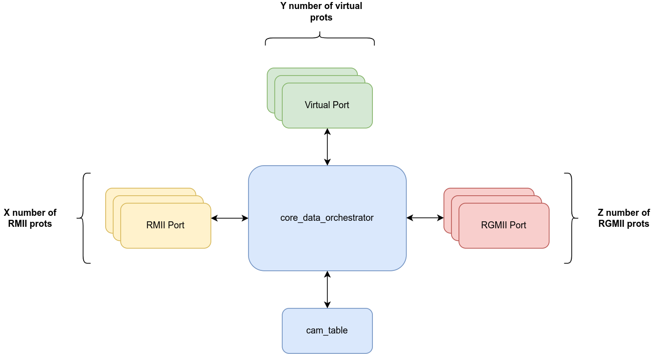
Passe Passe is a Layer 2 FPGA network switch with the capability of having a configurable of RMII, RGMII, or Virtual Ports. When configured with only one physical port (just a RGMII or RMII) and a virtual port, it can be used only FPGA designs that just want to send and receive data from a single port without any switching. As a Layer 2 network switch Passe Pasee will forward Ethernet packets to ports based on the MAC addresses. When an Ethernet frame is received by any of the ports, the mac source will be recorded and linked to the receiving port. This information is saved in a look up table. Next the mac destination is used to determine which port the frame was be forwarded to. If the mac source is found in the look up table, then the frame will be forwarded to the corresponding port. If the mac source is not found in the table, the data is broadcasted out of all the ports except the port it came from.
Example Configuration:
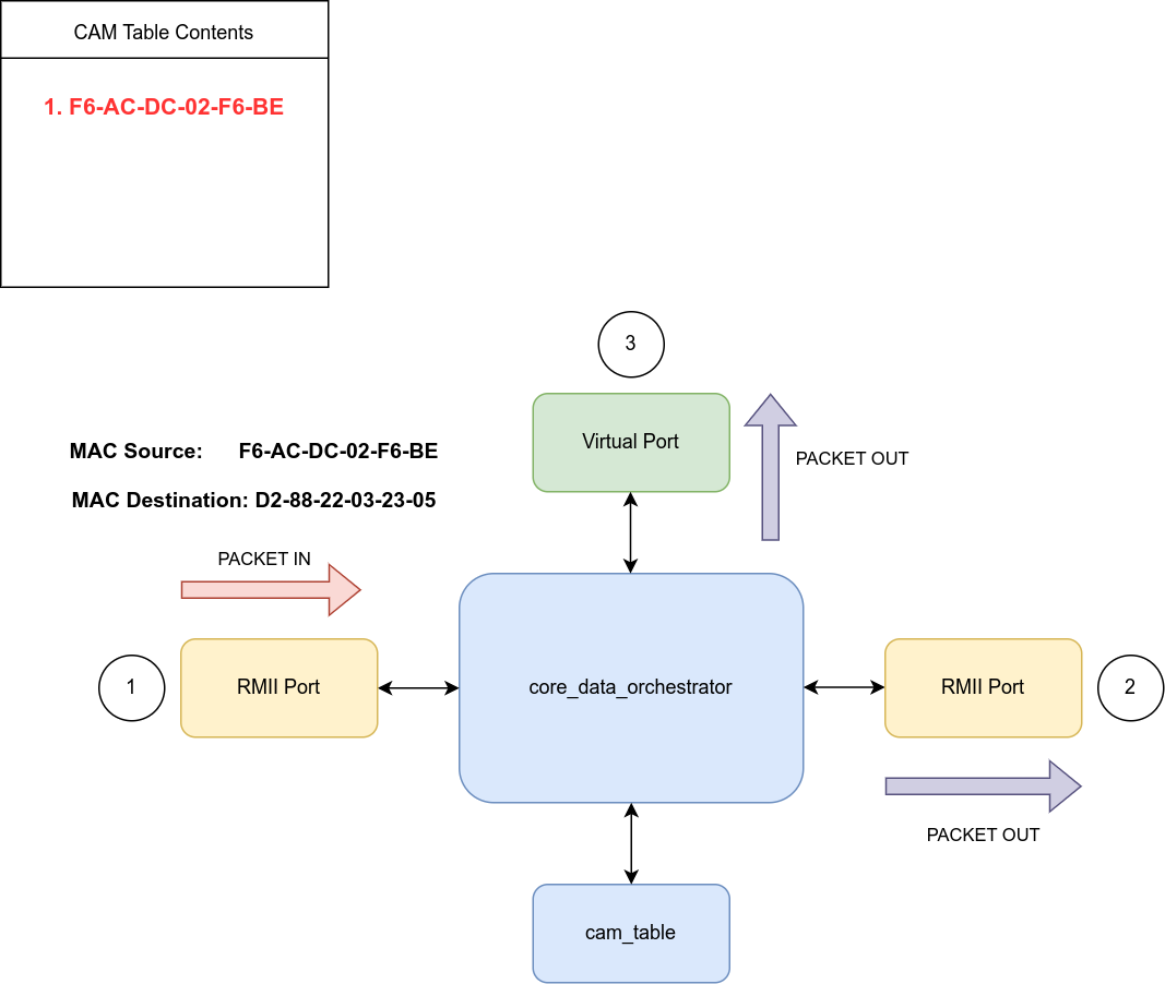
Below we will walk through switch routing using an example configuration of two physical RMII ports and one virtual port. The first packet will come in Port 1 (a RMII port) and will contain a mac source address of F6-AC-DC-02-F6-BE and a mac destination address of D2-88-22-03-23-05. Once the packet is parsed by the RMII port and is verified to have a valid CRC32 checksum, it will push the packet to the core data orchestrator. The core data orchestrator will parse the mac source and update the CAM table. Since this incoming packet has a mac source of F6-AC-DC-02-F6-BE, it will note that a device with mac address F6-AC-DC-02-F6-BE is connected to port 1. It will then scan the contents of the CAM table to see if there a match for the mac destination of the packet, D2-88-22-03-23-05. Since no such entry exists in the CAM table, the packet will be sent out of all ports except the one it arrived in (Port 1).
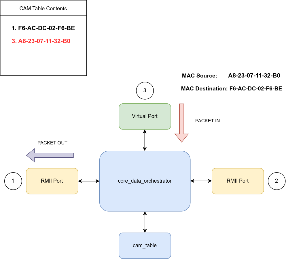
Afterwards a packet is generated by the virtual port and sent to core_data_orchestrator. This time the mac source of the packet is A8-23-07-11-32-B0 and the mac destination is F6-AC-DC-02-F6-BE. When core_data_orchestrator parses this packet it will add to the CAM table an entry indicating that a device with a mac address of A8-23-07-11-32-B0 is connected to port 3. It will then scan the CAM table to see if there is an entry with a mac address that is equal to that of the mac destination of the parsed packet. This time the mac destination of F6-AC-DC-02-F6-BE does exist in the CAM table because it was added when the first packet was sent to the core. Therefore, core_data_orchestrator will send the packet out only to Port 1 which the port associated with the given mac destination in the CAM table.
Key Module Descriptions
RMII Port
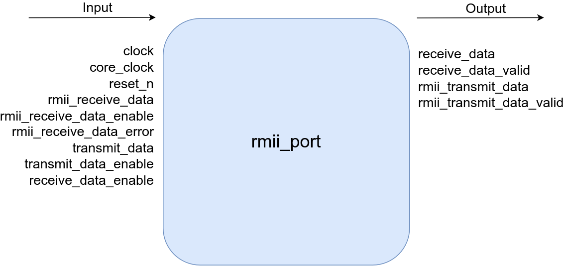
RMII stands for Reduced media-independent interface and is a standard that standards the signals that are needed to interact with a RMII PHY. The rmii_port module is the top level module that houses all the modules used to parse and transmit Ethernet packets that come in and and out of a RMII phy. Pictured below is the data flow for both receiving packets and transmitting packets.
| Name | Direction | Type | Width | Description |
|---|---|---|---|---|
| clock | input | wire | 1 | 50 MHz RMII port |
| core_clock | input | wire | 1 | main switch core clock |
| reset_n | input | wire | 1 | active low asynchronous reset |
| rmii_receive_data | input | wire | 2 | rmii data from phy |
| rmii_receive_data_enable | input | wire | 1 | active high rmii data valid from phy |
| rmii_receive_data_error | input | wire | 1 | active high rmii data error from phy |
| transmit_data | input | wire | 9 | data from switch, 9th bit (start bit) is set for first word of a stream |
| transmit_data_enable | input | wire | 1 | active high data valid from switch core |
| receive_data_enable | input | wire | 1 | active high signal indicating switch core is ready to accept data |
| receive_data | output | wire | 9 | data to switch, 9th bit (start bit) is set for first word |
| receive_data_valid | output | wire | 1 | data valid for data sent to switch core |
| rmii_transmit_data | output | wire | 2 | data sent to rmii phy |
| rmii_transmit_data_valid | output | wire | 1 | active high valid flag for data sent to rmii phy |
| XILINX | parameter | If non zero will use XILINX xpm IP for FIFOs and block ram |
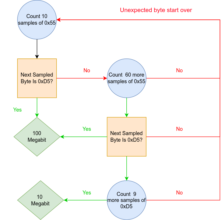
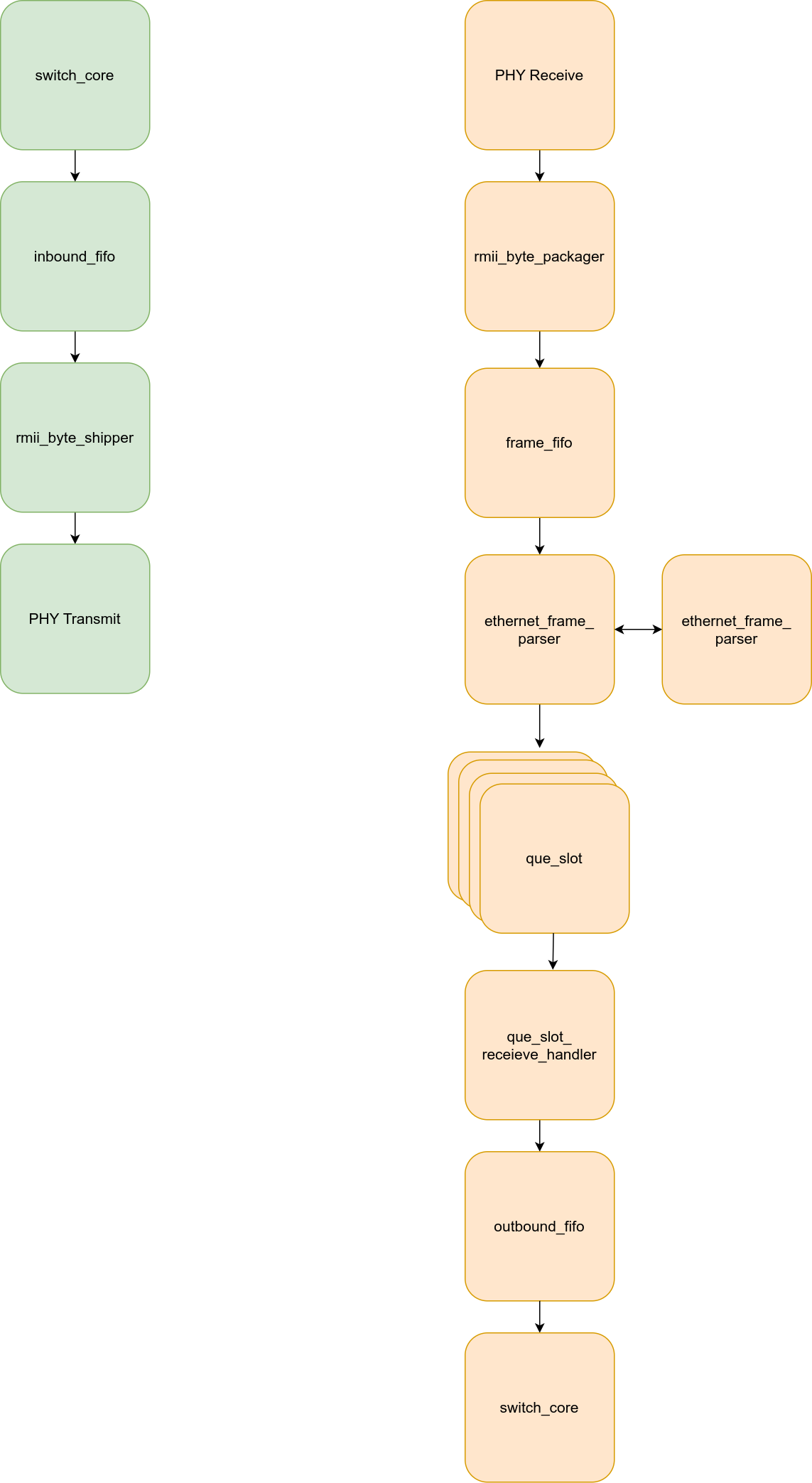
When receiving data from a RMII port data is processed as shown in the figure below. The first stage of data processing occurs in the rmii_byte_packager module. Here RMII data received from the RMII phy is packaged into bytes. This packaged byte stream is then combed through to find the preamble followed by the start of frame byte delimiter. As specified in the IEEE 802.3 standard, this sequence consists of 7 bytes of hex 0x55 followed by one byte of hex 0xD5. The "rmii_byte_packager" module will also determine the speed at which the RMII port is operating. Using the 50MHz RMII reference clock the module will count how many preamble bytes it receives. If it samples 7 premable bytes followed by the start of frame byte it determines that it is operating at 100 Megabit per second. However if it samples 70 preamble bytes followed by 10 start of frame bytes it determines the operating speed is 10 Megabit per second. This determined speed is communicated to the transmitting modules so that packets are also transmitted at the same speed at which they are recieved.
Once this sequence has been found it will begin pushing following packaged Ethernet frame bytes to the frame_fifo. The frame fifo is 9 bits wide and the most significant bit is used as a start bit, therefore the first word in the fifo for any new frame will consist of the 9th bit set and the following 8 bits will be first byte of the MAC destination.
The module named Ethernet_frame_parser will read data from the fifo and begin checking received Ethernet frames CRC32 (also known as the frame check sequence). If the CRC32 is valid, the frame will be committed to a slot which is essentially a fifo that is capable of holding a single Ethernet frame. The number of available que slots is parameterized and a larger number will allow more frames to be qued up without dropping frames. If all frame slots are full, ethernet_frame_parser will drop the frame. If the CRC32 of the frame is incorrect, the frame will not be committed and the que slot that was receiving the faulty frame will be reset.
Further down the data path, a module named que_receive_slot_handler will scan each que slot in a round robin fashion. If any of the que slots are filled with a valid frame it will push the data from the que slot to the outbound fifo. The outbound fifo is an asynchronous FIFO which connects to the core data orchestrator. This fifo is the final stage of the RMII port data path and is a 9 bit wide fifo with the most significant bit being a start bit similar to the frame fifo mentioned earlier. The read side of outbound_fifo is connected to the switch core.
When receiving data form the switch core, the data path is much shorter. The switch core will deliver a frame byte stream to the inbound_fifo. Like the outbound_fifo this is a 9 bit wide fifo with the most significant bit being the start bit that indicates the start of a new frame. The frames in this FIFO do not include the preamble of start of frame delimiter. A module named rmii_byte_shipper reads data from the inbound_fifo and pushes it to the RMII PHY.
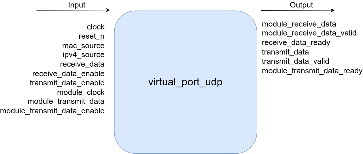
Virtual Port
The virtual port allows modules internal to the FPGA fabric to send and receive IPV4 UDP packets. Essentially the virtual port acts an internal port connected to the switch. Transmitting data using the virtual port does not require a module to construct a full Ethernet frame with correct checksum. The frame construction is handled by the virtual port and a module is only required to supply the following: The MAC destination, the IPV4 destination, the UDP datagram payload size, the UDP source, UDP destination, and the UDP datagram payload.
| Name | Direction | Type | Width | Description |
|---|---|---|---|---|
| clock | input | wire | 1 | main clock |
| reset_n | input | wire | 1 | active low asynchronous reset |
| mac_source | input | wire | 48 | mac source of the port |
| ipv4_source | input | wire | 32 | ipv4 source of the port |
| receive_data | input | wire | 9 | Ethernet frame data received from the switch core, the 9th bit is set for the first word of the frame |
| receive_data_enable | input | wire | 1 | active high valid flag for data coming from switch core |
| transmit_data_enable | input | wire | 1 | active high flag indicating switch is ready to digest an Ethernet frame from this port |
| module_clock | input | wire | 1 | clock used by modules who receive/transmit from/to switch core using the virtual port feature |
| module_transmit_data | input | wire | 9 | data from fabric modules who wish to transmit via the virtual port |
| module_transmit_data_enable | input | wire | 1 | active high data valid from fabric modules |
| module_receive_data | output | wire | 9 | data sent to fabric modules from virtual port, the 9th bit is set for the first word of a new set of data (start bit) |
| module_receive_data_valid | output | wire | 1 | active high data valid for data sent to fabric modules |
| receive_data_ready | output | wire | 1 | active high flag from port indicating it is ready to receive data from the switch core |
| transmit_data | output | wire | 9 | Ethernet frame data transmitted to the switch core, the 9th bit is set for the first word of the frame |
| transmit_data_valid | output | wire | 1 | active high valid flag for data transmitted to switch core |
| module_transmit_data_ready | output | wire | 1 | active high flag indicating port is ready to take data from fabric modules |
| XILINX | parameter | If non zero will use XILINX xpm IP for FIFOs and block ram |
The virtual port is also capable of transmitting fragmented IP packets, so the module does not need to fragment large payloads. This simple solution abstracts away the complexities of constructing and transmitting Ethernet frames and only requires the user to provide some metadata. Addtionaly complexities of parsing and verifying received Ethernet frames is also handles by the virtual port. When the virtual port receives an Ethernet frame from the switch core, it will check the validity of the frame by verifying checksums, verifying it is a IPV4 UDP frame, and will even reconstruct fragmented IP packets. Once the frame has been validated and parsed, the virtual port will output a byte stream containing the following: The MAC source, IPV4 destination, IPV4 source, UDP source, UDP destination, UDP datagram payload size, and finally the UDP datagram payload.
With this information, the user is free to process the received data in anyway they see fit.
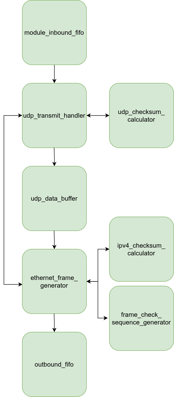
When a module a wants to transmit data, its interface to the virtual port is the module_inbound_fifo. This is just a normal FIFO which should allow the virtual port to be incorporated to any FPGA project with ease.
This FIFO accepts 9 bit data where the most significant bit is used as a start bit. The data structure that should be written to the FIFO is highlighted in the table below.
| Name | Data |
|---|---|
| MAC Destination Byte 0 | {1'b1, 8'hXX} |
| MAC Destination Byte 1 | {1'b0, 8'hXX} |
| MAC Destination Byte 2 | {1'b0, 8'hXX} |
| MAC Destination Byte 3 | {1'b0, 8'hXX} |
| MAC Destination Byte 4 | {1'b0, 8'hXX} |
| MAC Destination Byte 5 | {1'b0, 8'hXX} |
| IPV4 Destination Byte 0 | {1'b0, 8'hXX} |
| IPV4 Destination Byte 1 | {1'b0, 8'hXX} |
| IPV4 Destination Byte 2 | {1'b0, 8'hXX} |
| IPV4 Destination Byte 3 | {1'b0, 8'hXX} |
| UDP Datagram Size MSB | {1'b0, 8'hXX} |
| UDP Datagram Size LSB | {1'b0, 8'hXX} |
| UDP Source MSB | {1'b0, 8'hXX} |
| UDP Source LSB | {1'b0, 8'hXX} |
| UDP Destination MSB | {1'b0, 8'hXX} |
| UDP Destination LSB | {1'b0, 8'hXX} |
| UDP Datagram Bytes | N x {1'b0, 8'hXX} |
| Name | Data |
|---|---|
| MAC Destination Byte 0 | {1'b1, 8'hF6} |
| MAC Destination Byte 1 | {1'b0, 8'h90} |
| MAC Destination Byte 2 | {1'b0, 8'h2A} |
| MAC Destination Byte 3 | {1'b0, 8'h94} |
| MAC Destination Byte 4 | {1'b0, 8'h2D} |
| MAC Destination Byte 5 | {1'b0, 8'h5E} |
| IPV4 Destination Byte 0 | {1'b0, 8'hF0} |
| IPV4 Destination Byte 1 | {1'b0, 8'hF1} |
| IPV4 Destination Byte 2 | {1'b0, 8'hF2} |
| IPV4 Destination Byte 3 | {1'b0, 8'hF3} |
| UDP Datagram Size MSB | {1'b0, 8'h00} |
| UDP Datagram Size LSB | {1'b0, 8'h02} |
| UDP Source MSB | {1'b0, 8'h44} |
| UDP Source LSB | {1'b0, 8'h44} |
| UDP Destination MSB | {1'b0, 8'h22} |
| UDP Destination LSB | {1'b0, 8'h22} |
| UDP Datagram Bytes | {1'b0, 8'hAC} |
| UDP Datagram Bytes | {1'b0, 8'hDC} |
The module named udp_transmit_handler is connected to the read side of the FIFO and is responsible for handling this data. It's primary goals are to calculate the UDP checksum, handle the fragmentation of packets if the UDP datagram size is too large, and to command the ethernet_frame_generator module to actually construct and send the frame. In order to calculate the UDP checksum, the data is buffered into the block ram labeled as the udp_data_buffer. We must buffer the data first because we do not know what the UDP checksum until we process all the data and we cannot begin constructing an Ethernet frame before we know the checksum since the checksum field is before the data fields.
Once the data has been buffered and the UDP checksum has been calculated, udp_transmit_handler will begin commanding the ethernet_frame_generator module to construct and output an Ethernet frame.
The ethernet_frame_generator module is a simple state machine that has a state for each part of the Ethernet frame. It's sole purpose is to construct a full IPV4 UDP frame using the information and data supplied by udp_transmit_handler and the udp_data_buffer. The outputted frame is pushed to the outbound_fifo.
The outbound_fifo is the final stage of this data flow process and it’s output is connected to the switch core. Like all the other outbound port FIFOs, this FIFO also operates using 9 bit words where the most significant bit indicates the start of a frame.
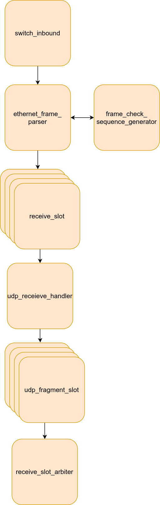
The virtual port receives data from switch core in the same way the ports do. The switch core will write data to the switch_inbound FIFO which is a 9 bit wide FIFO that holds full Ethernet frames with the the most significant bit being a start bit used to indicate the start of a frame.
The read port of the FIFO is connected to the ethernet_frame_parser module. As the name suggests this module will parse the incoming data stream and identify each portion of the Ethernet frame. This module will push the MAC source, IPV4 source, IPV4 destination, UDP Source, UDP Destination, UDP Length, and UDP datagram to a receive_slot. The receive slots are modules that buffer the previously mentioned data and keep track of the packet fragmentation info so packets can be reconstructed.
The Ethernet frame parser will also verify the frame check sequence of the incoming frame. If the frame is invalid, the receive_slot will be reset and the faulty data will be flushed. If no empty receive slots are available, the packet will be dropped. The number of receive slots can be adjusted using the RECEIVE_QUE_SLOTS parameter. It is recommended to adjust the number of slots depending on the amount of traffic the port is expected to see.
Next, the udp_receive_handler will check read from receive slots in a round robin fashion searching for a start bit. If a start bit is found, it will drain the receive slot and push the data to a udp_fragment_slot. These slots are similar to the receive que slots except they are designed to group any fragmented data together. The udp_receive_handler will check if the data is a fragment and will push it to the matching fragment slot.
The number of fragment slots can be adjusted using the FRAGMENT_SLOTS parameter. It is recommend to adjust the number of slots depending on the number of fragmented packets the port is expected to see.
Once a fragment slot has received all of its data, it will be marked as ready. The receive_slot_arbiter module will check each fragment slot in a round robin fashion, looking for any ready fragment slots. If one is found, it will be drained and pushed out of the virtual port 9 bits at a time, with the most significant bit being a start bit. The format of this pushed out data is described in the table below.
| Name | Data |
|---|---|
| MAC Source Byte 0 | {1'b1, 8'hXX} |
| MAC Source Byte 1 | {1'b0, 8'hXX} |
| MAC Source Byte 2 | {1'b0, 8'hXX} |
| MAC Source Byte 3 | {1'b0, 8'hXX} |
| MAC Source Byte 4 | {1'b0, 8'hXX} |
| MAC Source Byte 5 | {1'b0, 8'hXX} |
| IPV4 Destination Byte 0 | {1'b0, 8'hXX} |
| IPV4 Destination Byte 1 | {1'b0, 8'hXX} |
| IPV4 Destination Byte 2 | {1'b0, 8'hXX} |
| IPV4 Destination Byte 3 | {1'b0, 8'hXX} |
| IPV4 Source Byte 0 | {1'b0, 8'hXX} |
| IPV4 Source Byte 1 | {1'b0, 8'hXX} |
| IPV4 Source Byte 2 | {1'b0 ,8'hXX} |
| IPV4 Source Byte 3 | {1'b0, 8'hXX} |
| UDP Length Size MSB | {1'b0, 8'hXX} |
| UDP Length Size LSB | {1'b0, 8'hXX} |
| UDP Data Gram Bytes | N x {1'b0, 8'hXX} |
Core Data Orchestrator
The module responsible to routing data to ports is known as core_data_orchestrator. Each has a input and output FIFO connected to core_data_orchestrator. The FIFOs must have a width of nine bits and the depth can be customized depending on the amount of traffic a port is expected to handle.
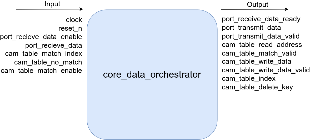
To enable this behavior core_data_orchestrator consists of a state machine that loops through the ports in a round robin format, parses their frame data, updates the cam table, and then forwards the frame to the appropriate port(s). The states of this finite state machine are described below.
1. S_FIND_START_BIT
This is the initial state of the FSM. In this state each input data FIFO is checked in a round robin fashion. A 9 bit word is pulled from the FIFO. If no start bit is found, the pulled word is discarded and the next FIFO is checked in a round robin fashion. If the start bit (9th bit) is set, the FSM will continue to the next state and save the pulled byte as part of the MAC destination.
2. S_GET_MAC_DESTINATION
Five more bytes are pulled until all the MAC destination bytes are captured. Once the bytes constituting the MAC destination are captured, the FSM will move to the next state.
3. S_GET_MAC_SOURCE
Six bytes constituting the MAC source are pulled from the FIFO and the FSM moves on to the next state.
4. S_LOOKUP_SOURCE_PORT
Checks to see if the MAC source exists in the CAM table. If it does not exist it will go to the S_UPDATE_TABLE state to add it. If it does exist but the port number has changed, it will delete the stale entry by going to the S_DELETE_OLD_KEY state.
5. S_DELETE_OLD_TABLE_ENTRY
Deletes the existing MAC source entry if the port associated to that MAC source has changed.
6. S_UPDATE_TABLE
Now that we know what the mac source of the received packet is, we can update our CAM table and map the port number to the MAC source.
7. S_LOOKUP_DESTINATION_PORT
Next we check if an entry exists for the mac destination in our CAM table. If an entry exists we know to transmit to that port. If an entry does not exist, we must forward it out of all the ports except the one the packet originated from.
8. S_TRANSMIT_MAC_DESTINATION
First we forward the previously pulled MAC destination data.
9. S_TRANSMIT_MAC_SOURCE
Then we forward the previously pulled MAC source data.
10. S_TRANSMIT_DATA
Next we pull data from the input FIFO and transmit that data out the target ports. We continue to do this until there is no more data or a new start bit is found. If either of those conditions are met, the FSM will loop back to the S_FIND_START_BIT state.
Supplemetary Module Descriptions
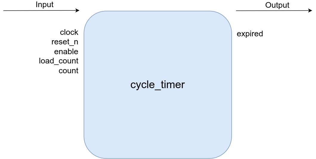
Cycle Timer
A timer that counts a configurable number of clock cycles and outputs whether or not the count has been completed. This module can be used as a timeout timer or just a clock cycle counter.
| Name | Direction | Type | Width | Description |
|---|---|---|---|---|
| clock | input | wire | 1 | main system clock |
| reset_n | input | wire | 1 | active low asynchronous reset |
| enable | input | wire | 1 | active high enable signal to start counter |
| load_count | input | wire | 1 | active high signal to reload timer with supplied count value |
| count | input | wire | BIT_WIDTH | initial count value for timer |
| expired | output | logic | 1 | active high flah indicating timer has finished counting |
| BIT_WIDTH | parameter | bit width of the counter |
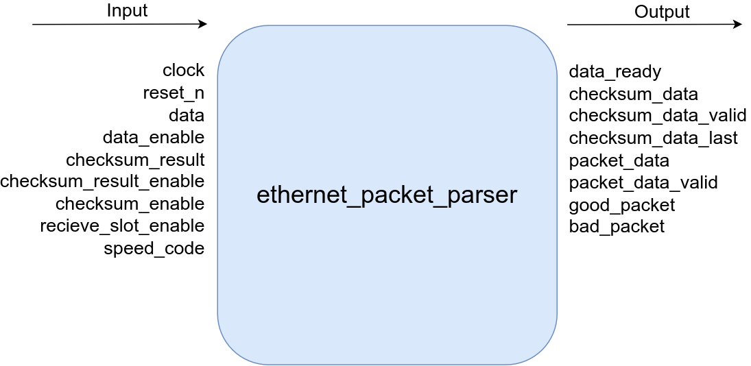
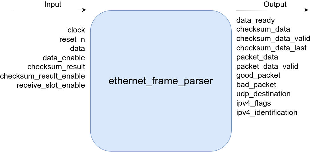
Ethernet Packet Parser
This module is used in non virtual ports to parse a given 802.3 Ethernet packet and verifies if it has a correct frame check sequence or not. As it parses the frame it will pass it out to a receive slot. If the frame has an incorrect checksum, it will pulse the bad packet flag. If the frame is good the good packet flag will be pulsed.
| Name | Direction | Type | Width | Description |
|---|---|---|---|---|
| clock | input | wire | 1 | main system clock |
| reset_n | input | wire | 1 | active low asynchronous reset |
| data | input | wire | 9 | Ethernet frame data |
| data_enable | input | wire | 1 | active high ethernet frame data valid |
| checksum_result | input | wire | 32 | calculated frame check sequence result |
| checksum_result_enable | input | wire | 1 | active high flah indicating calculated frame check sequence result is valid |
| receive_slot_enable | input | wire | RECEIVE_QUE_SLOTS | active high flag indicating receive slot is able to accept data |
| speed_code | input | wire | 2 | Ethernet link speed, 2 =Gigabit, 1 =100 Megabit, 0 = 10 Megabit |
| data_ready | output | logic | 1 | active high flag indicating module is ready to parse Ethernet frame byte |
| checksum_data | output | reg | 8 | byte of data sent to CRC32 checksum calculator module |
| checksum_data_valid | output | reg | 1 | active high flag indicating byte being sent to CRC32 checksum calculator is valid |
| checksum_data_last | output | reg | 1 | active high flag indicating the last byte of data has been sent to the CRC32 calculator |
| packet_data | output | reg | 8 | processed ethernet frame data, the first processed word has the 9th bit set |
| packet_data_valid | output | reg | RECEIVE_QUE_SLOTS | active high valid flag for processed Ethernet frame word |
| good_packet | output | reg | RECEIVE_QUE_SLOTS | active high pulse indicating the processed Ethernet frame is valid |
| bad_packet | output | reg | RECEIVE_QUE_SLOTS | active high pulse indicating the processed Ethernet frame is not valid |
| RECEIVE_QUE_SLOTS | parameter | number of data slots that frames can be deposited in, increase this number to handle more traffic |
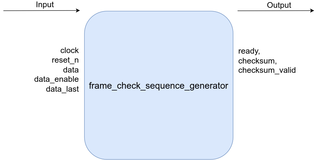
Frame Check Sequence Generator
Takes in a byte stream and returns the CRC32 of the byte stream when the “last byte” input is pulsed.
| Name | Direction | Type | Width | Direction |
|---|---|---|---|---|
| clock | input | wire | 1 | main system clock |
| reset_n | input | wire | 1 | active low asynchronous reset |
| data | input | wire | 8 | data to be check summed |
| data_enable | input | wire | 1 | active high flag indicating received data is valid and should be used for the current calculation |
| data_last | input | wire | 1 | active high pulse indicating the last byte to be used for the current checksum calculation has been sent |
| ready | output | reg | 1 | active high flag indicating module is ready to accept calculate checksums |
| checksum | output | reg | 32 | last calculated checksum valid |
| checksum_valid | output | reg | 1 | active high pulse indicating a new calculated checksum is available |
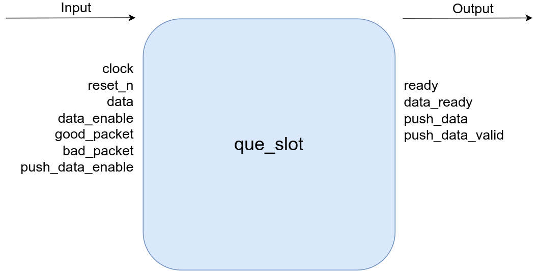
Que Slot
Holds a single 802.3 Ethernet frame that is given to it by the “ethernet_packet_parser”. The number of que slots is parameterized. It is recommend to scale the number of que slots relative to the expected traffic of the given port.
| Name | Direction | Type | Width | Description |
|---|---|---|---|---|
| clock | input | wire | 1 | main system clock |
| reset_n | input | wire | 1 | active low asynchronous reset |
| data | input | wire | 8 | incoming data to be saved in que slot |
| data_enable | input | wire | 1 | data valid for incoming data |
| good_packet | input | wire | 1 | active high pulse meaning the previously received data should be kept |
| bad_packet | input | wire | 1 | active high pulse that will reset the internal fifo and flush out the previously received data |
| push_data_enable | input | wire | 1 | active high signal meaning the down stream module is ready to accept qued data |
| ready | output | reg | 1 | active high flag indicating slot is empty and ready to accept data |
| data_ready | output | reg | 1 | active high flahg indicating slot is filled with valid data and ready to be drained |
| push_data | output | logic | 8 | drained datam first word of drained data will have the 9th bit (start bit) set |
| push_data_valid | output | logic | 1 | active high valid flag for drained data |
| XILINX | parameter | If non zero will use XILINX xpm IP for FIFOs and block ram |
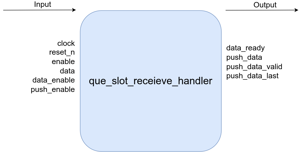
Que Slot Receive Handler:
Iterates through que slots in a round robin fashion. If it finds a que slot that is populated and ready, it will push its contents to the outbound fifo that is connected to the switch core.
| Name | Direcction | Type | Width | Description |
|---|---|---|---|---|
| clock | input | wire | 1 | main system clock |
| reset_n | input | wire | 1 | active low asynchronous reset |
| enable | input | wire | 1 | active high master enable for handler |
| data | input | wire | RECEIVE_QUE_SLOTS x 8 | data incoming into receive slot |
| data_enable | input | wire | RECEIVE_QUE_SLOTS | data valid for incoming data |
| push_enable | input | wire | RECEIVE_QUE_SLOTS | active high signal indicating the bit indexed receive slot is ready to be drained |
| data_ready | output | logic | RECEIVE_QUE_SLOTS | active high signal indicating the bit indexed receive slot is ready to accept data |
| push_data | output | reg | 9 | data captured from a seelcted receive slot, 9th bit is set for the first byte |
| push_data_valid | output | reg | 1 | active high valid flag for data captured from selected receive slot |
| push_data_last | output | reg | 1 | active high pulse indicating the last byte has been drained from the selected receive slot |
| RECEIVE_QUE_SLOTS | parameter | number of slots that are connected to this module |
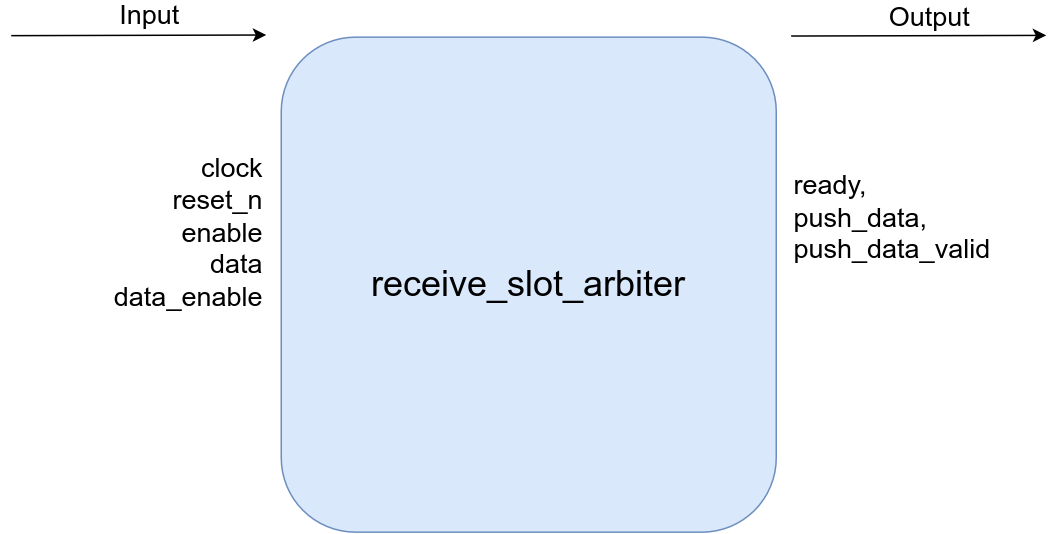
Receive Slot Arbiter:
Iterates through fragment slots in a round robin fashion. If it finds a fragment slot that is populated and ready, it will push its contents to the outbound fifo that is connected to the switch core.
| Name | Direction | Type | Width | Description |
|---|---|---|---|---|
| clock | input | wire | 1 | main system clock |
| reset_n | input | wire | 1 | active low asynchronous reset |
| enable | input | wire | RECEIVE_QUE_SLOTS | active high signal from a slot meaning it is ready to release its data |
| data | input | wire | RECEIVE_QUE_SLOTS x 8 | data from slot |
| data_enable | input | wire | RECEIVE_QUE_SLOTS | active high data valid from slot |
| ready | output | logic | RECEIVE_QUE_SLOTS | active high signal sent to a slot inidicating module is ready to read data |
| push_data | output | logic | 9 | data passed through from selected slot, first bit is set |
| push_data_valid | output | reg | 1 | active high data valid for data passed through from slot |
| RECEIVE_QUE_SLOTS | parameter | number of slots that are connected to this module |
RMII Byte Packager:
Takes in data from a RMII phy and outputs the received data in byte format. It will also detect if the data is being sent at 100 Megabit or 10 Megabit.
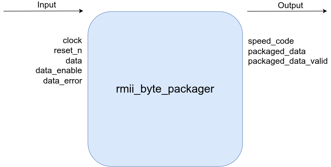
| Name | Direction | Type | Width | Description |
|---|---|---|---|---|
| clock | input | wire | 1 | main system clock |
| reset_n | input | wire | 1 | active low asynchronous reset |
| data | input | wire | 2 | data from rmii phy |
| data_enable | input | wire | 1 | data valid from phy |
| data_error | input | wire | 1 | data error from phy |
| packaged_data | output | reg | 9 | rmii data concatendated as bytes, the 9th bit (start bit) is set for the first byte of a new data strem received from the phy |
| packaged_data_valid | output | reg | 1 | data valid for the concatendated byte |
| speed_code | output | reg | 2 | data speed detected by packager |
Internet Checksum Calculator:
Calculated the IPV4/UDP checksum of a given byte stream and outputs the result when the last byte input is asserted.
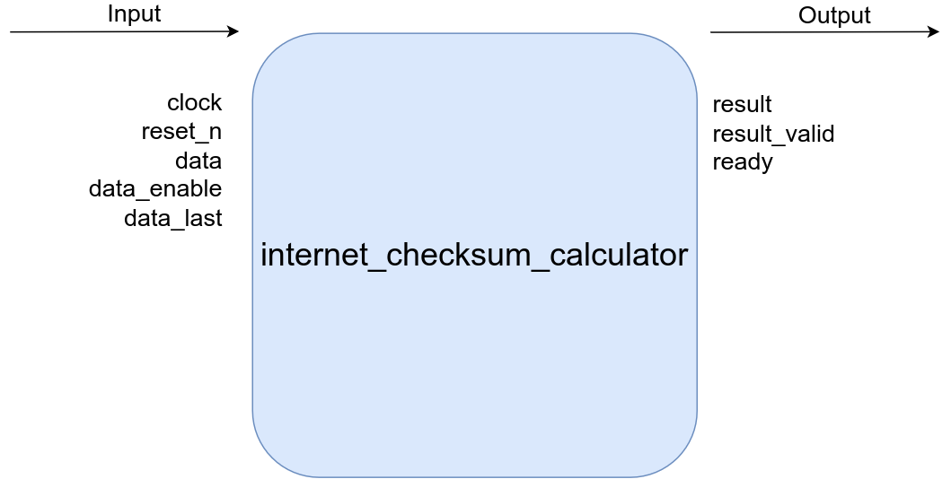
| Name | Direction | Type | Width | Description |
|---|---|---|---|---|
| clock | input | wire | 1 | main clock |
| reset_n | input | wire | 1 | active low asynchronous reset |
| data | input | wire | 8 | data byte to be checksumed |
| data_enable | input | wire | 1 | active high valid for data to be checksummed |
| data_last | input | wire | 1 | active high flag indicating the last byte for the current checksum has been supplied |
| result | output | reg | 16 | checksum result |
| result_valid | output | reg | 1 | active high valid flag for checksum result |
| ready | output | reg | 1 | active high flag indicating calculator is ready to accept new byte for the current checksum calculation |
Receive Slot:
Holds data that is parsed by the Ethernet frame parser inside the virtual port. If the parsed frame is valid the data will be held until it is processed by the udp receive handler, otherwise the data is flushed and the slot is reset.
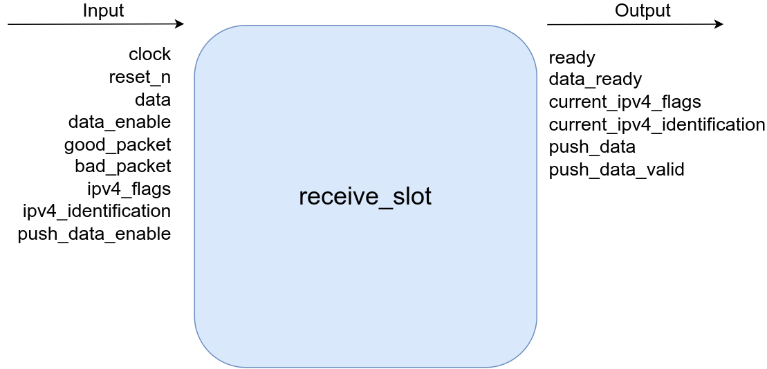
| Name | Direction | Type | Width | Description |
|---|---|---|---|---|
| clock | input | wire | 1 | main clock |
| reset_n | input | wire | 1 | active low asynchronous reset |
| data | input | wire | 8 | data to be written into slot |
| data_enable | input | wire | 1 | active high data valid for data written into slot |
| good_packet | input | wire | 1 | active high flag meaning data accumulated in slot is valid |
| bad_packet | input | wire | 1 | active high flag meaning data accumulated in slot is invalid and should be flushed |
| ipv4_flags | input | wire | 16 | ipv4 flags and fragment offset field of the current packet being received into the slot |
| ipv4_identification | input | wire | 16 | ipv4 identification field of the current packet being received into the slot |
| push_data_enable | input | wire | 1 | active high flag from the downstream module indicating it is ready to digest data stored in this slot |
| ready | output | reg | 1 | active high flag to upstream module indicating that slot is ready to take in data |
| data_ready | output | reg | 1 | active high flag indicating that the slot is full and ready to be drained |
| current_ipv4_flags | output | reg | 16 | ipv4 flags and fragment offset field of the current packet stored in the full slot |
| current_ipv4_identification | output | reg | 16 | ipv4 identification field of the current packet stored in the full slot |
| push_data | output | logic | 8 | data being pushed from slot to downstream module. The 9th bit is set for the first word pushed out (start bit) |
| push_data_valid | output | logic | 1 | active high data valid flag for data being pushed from slot to downstream module |
| XILINX | parameter | If non zero will use XILINX xpm IP for FIFOs and block ram |
UDP Fragment Slot:
Holds data that is deposited by the udp receive handler module. The data in these slots are grouped by IPV4 packet ID. Therefore, fragmented frames of the same ID are de fragmented and accumulated in these slots.
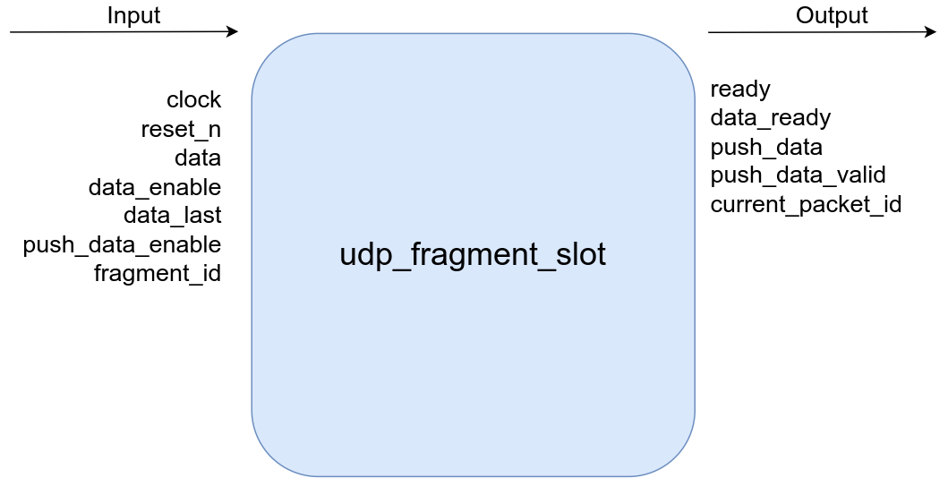
| Name | Direction | Type | Width | Description |
|---|---|---|---|---|
| clock | input | wire | 1 | main clock |
| reset_n | input | wire | 1 | active low asynchronous reset |
| data | input | wire | 8 | data to be written into slot |
| data_enable | input | wire | 1 | active high data valid for data written into slot |
| data_last | input | wire | 1 | active high flag indicating the last byte has been written into slot |
| push_data_enable | input | wire | 1 | active high flag from the downstream module indicating it is ready to digest data stored in this slot |
| fragment_id | input | wire | 16 | ipv4 fragment id of data being received into slot |
| ready | output | reg | 1 | active high flag to upstream module indicating that slot is ready to take in data |
| data_ready | output | reg | 1 | active high flag indicating that the slot is full and ready to be drained |
| push_data | output | logic | 9 | data being pushed from slot to downstream module. The 9th bit is set for the first word pushed out (start bit) |
| push_data_valid | output | logic | 1 | active high data valid flag for data being pushed from slot to downstream module |
| current_packet_id | output | reg | 16 | ipv4 identification of the packet being held in the slot |
| XILINX | parameter | If non zero will use XILINX xpm IP for FIFOs and block ram |
UDP Receive Handler:
Iterates through udp fragment slots in a round robin fashion. If it finds a slot that is populated and ready, it will push its contents out.
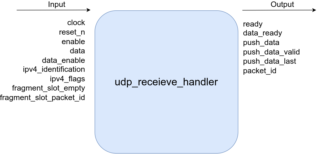
| Name | Direction | Type | Width | Description |
|---|---|---|---|---|
| clock | input | wire | 1 | main clock |
| reset_n | input | wire | 1 | active low asynchronous reset |
| enable | input | wire | RECEIVE_QUE_SLOTS | active high flag from upstream slot meaning the slot is ready to be processed |
| data | input | wire | RECEIVE_QUE_SLOTS x 8 | data from up stream slots |
| data_enable | input | wire | RECEIVE_QUE_SLOTS | active high valid for up stream slot data |
| ipv4_identification | input | wire | RECEIVE_QUE_SLOTS x 16 | ipv4 id from upstream slot |
| ipv4_flags | input | wire | RECEIVE_QUE_SLOTS x 16 | ipv4 flag and fragment offset from upstream slot |
| fragment_slot_empty | input | wire | RECEIVE_QUE_SLOTS | active high empty flag from downstream fragment slots |
| fragment_slot_packet_id | input | wire | RECEIVE_QUE_SLOTS x 16 | ipv4 identification from downstream fragment slots |
| data_ready | output | logic | RECEIVE_QUE_SLOTS | active high signal to upstream slot signifying handler is ready to accept more data from the slot |
| push_data | output | reg | 8 | data pushed from upstream slot to downstream slot |
| push_data_valid | output | reg | RECEIVE_QUE_SLOTS | active high valid from for data pushed downstream |
| push_data_last | output | reg | RECEIVE_QUE_SLOTS | active high pulse indicating the last |
| packet_id | output | reg | 16 | ipv4 id to downstream slot |
| RECEIVE_QUE_SLOTS | parameter | number of slots that are connected to this module |
UDP Transmit Handler:
This module orchestrates the transmitting of UDP data an internal module wishes to send. It will calculate the UDP checksum, fragment the data if needed, and then command the downstream Ethernet frame generator module to construct the frame.
![]()
| Name | Direction | Type | Width | Description |
|---|---|---|---|---|
| clock | input | wire | 1 | main clock |
| reset_n | input | wire | 1 | active low asynchronous reset |
| enable | input | wire | 1 | active high flag indicating downstream module is ready to construct and transmit a frame |
| data | input | wire | 9 | data containing metadata and payload data from upstream slot |
| data_enable | input | wire | 1 | active high valid flag for data coming from upstream slot |
| ipv4_source | input | wire | 32 | target ipv4 source of frame to be transmitted |
| data_ready | output | logic | 1 | active high flag indicating module is ready to receive data from upstream slot |
| mac_destination | output | ready | 48 | mac destination to be used for next transmitted frame |
| ipv4_destination | output | ready | 32 | ipv4 destination to be used for next transmitted frame |
| udp_destination | output | ready | 16 | udp destination to be used for the next transmitted frame |
| udp_source | output | ready | 16 | udp source to be used for the next transmitted frame |
| ipv4_identification | output | ready | 16 | ipv4 identification ot be used for the next transmitted frame |
| ipv4_flags | output | ready | 16 | ipv4 flags + fragment offset to be used for the next transmitted frame |
| udp_fragment_size | output | ready | 16 | number of udp datagram bytes the next frame will contain |
| udp_total_payload_size | output | ready | 16 | the total number of udp datagram bytes (sum of the datagram size of all fragment frames) |
| udp_buffer_write_address | output | ready | $clog2(UDP_TRANSMIT_BUFFER_SIZE) | write address to buffer containing udp datagram data |
| udp_buffer_data | output | ready | 8 | data written to buffer containing udp datagram data |
| udp_buffer_data_valid | output | ready | 1 | active high valid flag for data written to the buffer containing udp datagram data |
| udp_checksum_data | output | ready | 8 | data sent to udp checksum calculator |
| udp_checksum_data_valid | output | ready | 1 | active high valid flag for data sent to udp checksum calculator |
| udp_checksum_data_last | output | ready | 1 | active high flag indicating the last byte to the checksum calculator has been sent |
| transmit_valid | output | ready | 1 | active high control signal to enable the down stream frame generator |
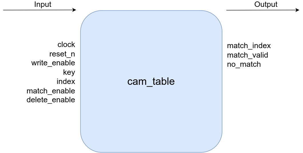
Cam Table
This table contains a list that maps ports connected to the switch to MAC addresses.
| Name | Direction | Type | Width | Description |
|---|---|---|---|---|
| clock | input | wire | 1 | main system clock |
| reset_n | input | wire | 1 | active low asynchronous reset |
| write_enable | input | wire | 1 | active high signal to write key value to able |
| key | input | wire | KEY_WIDTH | key value |
| index | input | wire | $clog2(INDEX_DEPTH) | index value |
| match_enable | input | wire | 1 | active high signal to find key entry in table |
| delete_enable | input | wire | 1 | active high signal to delete key entry from table |
| match_index | output | reg | $clog2(INDEX_DEPTH) | index value of matched key value |
| match_valid | output | reg | 1 | active high pulse indicating a key match was found after the user requested a match enable. If this not go high, no match was found and instead the “no_match” output will pulse |
| no_match | output | reg | 1 | active high pulse indicating a key match was NOT found after the user requested a match enable. If this not go high, no match was found and instead the “match_valid” output will pulse |
| KEY_WIDTH | parameter | number of bits the key values are, 48 bit for mac addresses | ||
| INDEX_DEPTH | parameter | number of entries in the table |
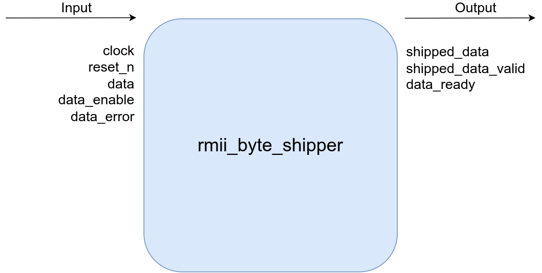
RMII Byte Shipper
Takes in byte data from a module and pushes it to a RMII phy. It will also construct a preamble sequence and start of frame.
| Name | Direction | Type | Width | Description |
|---|---|---|---|---|
| clock | input | wire | 1 | main clock |
| reset_n | input | wire | 1 | active low asynchronous reset |
| data | input | wire | 9 | data to be sent to rmii phy, 9th bit (start bit) set |
| data_enable | input | wire | 1 | active high data valid for received data |
| speed_code | input | wire | 2 | speed at which data should be transmitted to phy |
| shipped_data | output | reg | 2 | data to be sent to phy |
| shipped_data_valid | output | reg | 1 | active high data valid for data sent to phy |
| data_ready | output | logic | 1 | active high data valid for received data |
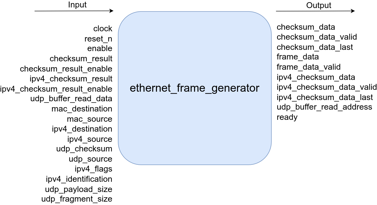
Ethernet Frame Generator
Takes in byte data from a module and pushes it to a RMII phy. It will also construct a preamble sequence and start of frame.
| Name | Direction | Type | Width | Description |
|---|---|---|---|---|
| clock | input | wire | 1 | main clock |
| reset_n | input | wire | 1 | active low asynchronous reset |
| enable | input | wire | 1 | active high control signal to start frame generation |
| checksum_result | input | wire | 32 | CRC32 frame check sequence result |
| checksum_result_enable | input | wire | 1 | active high valid flag for the CRC32 result |
| ipv4_checksum_result | input | wire | 16 | calculated ipv4 header checksum result |
| ipv4_checksum_result_enable | input | wire | 1 | active high valid signal for calculated ipv4 header checksum |
| udp_buffer_read_enable | input | wire | 8 | udp datagram data |
| mac_destination | input | wire | 48 | mac destination of the frame to be generated |
| mac_source | input | wire | 48 | mac source of the frame to be generated |
| ipv4_destination | input | wire | 32 | ipv4 destination of the frame to be generated |
| ipv4_source | input | wire | 32 | ipv4 source of the frame to be generated |
| udp_checksum | input | wire | 16 | udp checksum of the frame to be generated |
| udp_destination | input | wire | 16 | udp destination of the frame to be generated |
| udp_source | input | wire | 16 | udp source of the frame to be generated |
| ipv4_flags | input | wire | 16 | ipv4 flags + fragment offset field of frame to be generated |
| ipv4_identification | input | wire | 16 | ipv4 identification field of the frame to be generated |
| udp_payload_size | input | wire | 16 | total number of udp datagram bytes |
| udp_fragment_size | input | wire | 16 | number of udp datagram bytes for current fragment |
| checksum_data | output | logic | 8 | frame bytes to summed for the frame check sequence CRC32 |
| checksum_data_valid | output | logic | 1 | active high valid signal for frame bytes fed into CRC32 calculator |
| checksum_data_last | output | reg | 1 | active high pulse indicating the last byte to be considered for the CRC32 has been sent |
| frame_data | output | logic | 9 | generated Ethernet frame data, the 9th bit is set on the first byte of a new frame |
| frame_data_valid | output | logic | 1 | active high valid flag for generated Ethernet frame data |
| ipv4_checksum_data | output | reg | 8 | data fed to the ipv4 checksum calculator |
| ipv4_checksum_data_valid | output | reg | 1 | active high data valid for ipv4 checksum calculator |
| ivp4_checksum_data_last | output | reg | 1 | active high pulse indicating the last byte to be considered for the ipv4 checksum has been sent |
| udp_buffer_read_address | output | reg | $clog2(UDP_TRANSMIT_BUFFER_SIZE) | read address for the buffer containing the udp datagram |
| ready | output | reg | 1 | active high flag meaning generator is idle and ready to make a frame |
Ethernet Frame Parser
Receives and parses an ethernet frame. The frame must be IPV4 and UDP. If the frame is valid and the frame check sequence is correct (CRC32) it will pulse the good packet flag. If the frame is not valid for any reason it will pulse the bad packet flag.
| Name | Direction | Type | Width | Description |
|---|---|---|---|---|
| clock | input | wire | 1 | main clock |
| reset_n | input | wire | 1 | active low asynchronous reset |
| data | input | wire | 9 | Ethernet frame data to be parsed |
| data_enable | input | wire | 1 | active high data valid for frame data |
| checksum_result | input | wire | 32 | calculated CRC32 frame check sequence result |
| checksum_result_enable | input | wire | 1 | active high data valid for calculated CRC32 |
| receive_slot_enable | input | wire | RECEIVE_QUE_SLOTS | active high flag indicating slot is ready and able to accept frame data |
| data_ready | output | logic | 1 | active high flag indicating parser is ready to accept data |
| checksum_data | output | reg | 8 | data fed into CRC32 checksum calculator |
| checksum_data_valid | output | reg | 1 | active high valid flag for fed fed into CRC32 calculator |
| checksum_data_last | output | reg | 1 | active high flag indicating that the last byte has been supplied to the CRC32 calculator |
| packet_data | output | reg | 8 | parsed Ethernet frame data supplied to the slot |
| packet_data_valid | output | reg | RECEIVE_QUE_SLOTS | active high valid flag for data supplied to the slot |
| good_packet | output | reg | RECEIVE_QUE_SLOTS | active high flag indicating the parsed frame is good |
| bad_packet | output | reg | RECEIVE_QUE_SLOTS | active high flag indicating the parsed frame is not good |
| udp_destination | output | reg | 16 | udp destination field of parsed frame |
| ipv4_flags | output | reg | 16 | ipv4 flags + fragment offset field of the parsed frame |
| ipv4_identification | output | reg | 16 | ipv4 destination field of the parsed frame |
| RECEIVE_QUE_SLOTS | parameter | number of slots that are connected to this module |
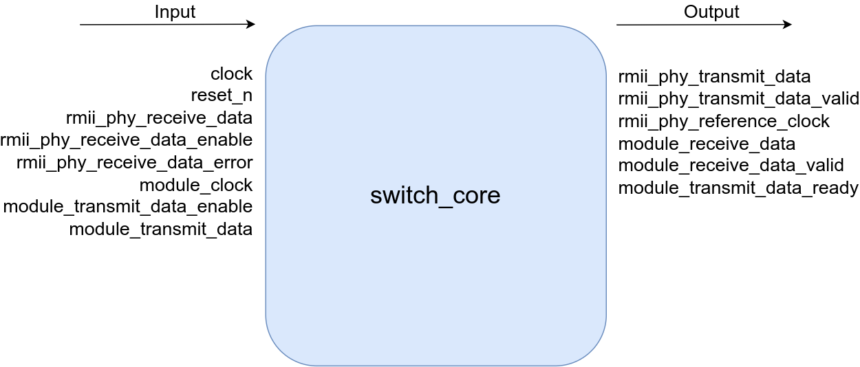
Switch Core
Top level module that houses all port modules and switch modules.
| Name | Direction | Type | Width | Description |
|---|---|---|---|---|
| clock | input | wire | 1 | main switch clock |
| reset_n | input | wire | 1 | active low asynchronous reset |
| rmii_clock | input | wire | NUMBER_OF_RMII_PORTS | 50 MHz RMII reference clock |
| rmii_phy_receive_data | input | wire | NUMBER_OF_RMII_PORTS x 2 | data received from RMII phy (RXD on PHY) |
| rmii_phy_receive_data_enable | input | wire | data valid from RMII phy (CRS_DV on PHY) | |
| rmii_phy_receive_data_error | input | wire | NUMBER_OF_RMII_PORTS | data error received from phy (RX_ER on PHY) |
| module_clock | input | wire | NUMBER_OF_VIRTUAL_PORTS | clock used by modules who receive/transmit from/to switch core using the virtual port feature |
| module_transmit_data_enable | input | wire | NUMBER_OF_VIRTUAL_PORTS | transmit data valid to virtual port |
| module_transmit_data | input | wire | NUMBER_OF_VIRTUAL_PORTS | transmit data to virtual port, 9th bit is set (start bit) during the start of a transmit |
| rmii_phy_transmit_data | output | wire | NUMBER_OF_RMII_PORTS | data sent to rmii phy (TXD on phy) |
| rmii_phy_transmit_data_valid | output | wire | NUMBER_OF_RMII_PORTS | data valid sent to phy (TX_EN on PHY) |
| module_receive_data | output | wire | NUMBER_OF_VIRTUAL_PORTS x 9 | data from virtual port to internal fabric modules |
| module_receive_data_valid | output | wire | NUMBER_OF_VIRTUAL_PORTS | data valid from virtual port to internal facbric modules |
| module_transmit_data_ready | output | wire | NUMBER_OF_VIRTUAL_PORTS | active high signal to internal fabric modules signifying virtual port is ready to digest data |
| NUMBER_OF_VIRTUAL_PORTS | parameter | number of virtual udp ports to be generated | ||
| NUMBER_OF_RMII_PORTS | parameter | number of RMII ports to be generated | ||
| XILINX | parameter | If non zero will use XILINX xpm IP for FIFOs and block ram |