
Brushed DC Motor Controller Design
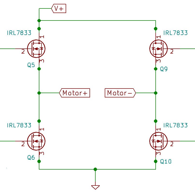
Hbridge Overview
The H bridge inverter is the preeminent method of controlling brushed DC motors or any bi-directional load. The Hbridge allows for supplying bi directional current to a load which in the case of DC motors allows clockwise and counter clockwise rotation.
Building a H bridge only requires four switches (mosfets, BJTs, or IGBTs). These switches allow the bridge two have effectively 4^2 states since there are 4 switches and each can be on or off. However, this doesn’t mean there are 16 states of operation as many of these states are useless and outright dangerous. A truth table of the states can be seen below where 1 means the switch is on and 0 means the switch is off.
![]()
| Switch 1 | Switch 2 | Switch 3 | Switch 4 | Bridge Status |
|---|---|---|---|---|
|
0 |
0 |
0 |
0 |
Floating load |
|
0 |
0 |
0 |
1 |
Floating load |
|
0 |
0 |
1 |
0 |
Floating load |
|
0 |
0 |
1 |
1 |
Grounded load |
|
0 |
1 |
0 |
0 |
Floating load |
|
0 |
1 |
0 |
1 |
Shoot through |
|
0 |
1 |
1 |
0 |
\(-V_{DC}\) across load |
|
0 |
1 |
1 |
1 |
Shoot through |
|
1 |
0 |
0 |
0 |
Floating load |
|
1 |
0 |
0 |
1 |
\(+V_{DC}\) across load |
|
1 |
0 |
1 |
1 |
Shoot through |
|
1 |
1 |
0 |
0 |
Floating Load |
|
1 |
0 |
1 |
1 |
Shoot through |
|
1 |
1 |
0 |
1 |
Shoot through |
|
1 |
1 |
1 |
0 |
Shoot through |
|
1 |
1 |
1 |
1 |
Shoot through |
Voltage Across Load
These modes are what make the hbridge such a useful circuit. These two states allow bi directional current flow across the load. This means a load such as a motor will be able to spin both clockwise and counter clockwise.
Shoot Through:
The most dangerous situation in hbridge operation is when a shoot through occurs. The almighty smoothening, also known as the destroyer of mosfets, is any case where there is a short between power and ground. In any mode where two series switches are active, a shoot through occurs.
Grounded Load:
When both points of the load are shorted to ground all current and any capacitance or inductive energy stores across the load is dumped to ground. When a motor is the load this state brakes the motor as quickly as possible (electrically speaking).
Recovery:
In the above states we mostly focused on delivering power to the load from a source, but with a motor we can also generate power and deliver it back to the source. The mechanical motion of a DC motor generates electric power in the form of a back emf. As the coil of a DC motor rotates, it cuts through the magnetic field provided by the permanent magnets inside the motor which creates a voltage across the coils. This means that the amount of back emf produced directly depends on the motors design. This generated voltage is a function of the back emf of the DC motor and the losses through the windings which can be calculated as:
$$V_m = iR + Ldi/dt + V_{emf}$$
$$V_{emf} = n/k_n$$
$$k_n =\ {k_e}^{-1}$$
$$n = revolutions\ per\ minute$$
$$k_e = electrical\ constant$$
$$Note:\ k_e\ and\ k_n\ are\ datasheet\ values$$
This power can be transferred directly back into the source if the back emf voltage is greater than the source (assuming you can dump charge back in to your source) or other more exotic power capturing methods can be employed.
Floating Load:
In this state there is no current flowing across the load in any direction. Ultimately this is a useless load that does nothing.
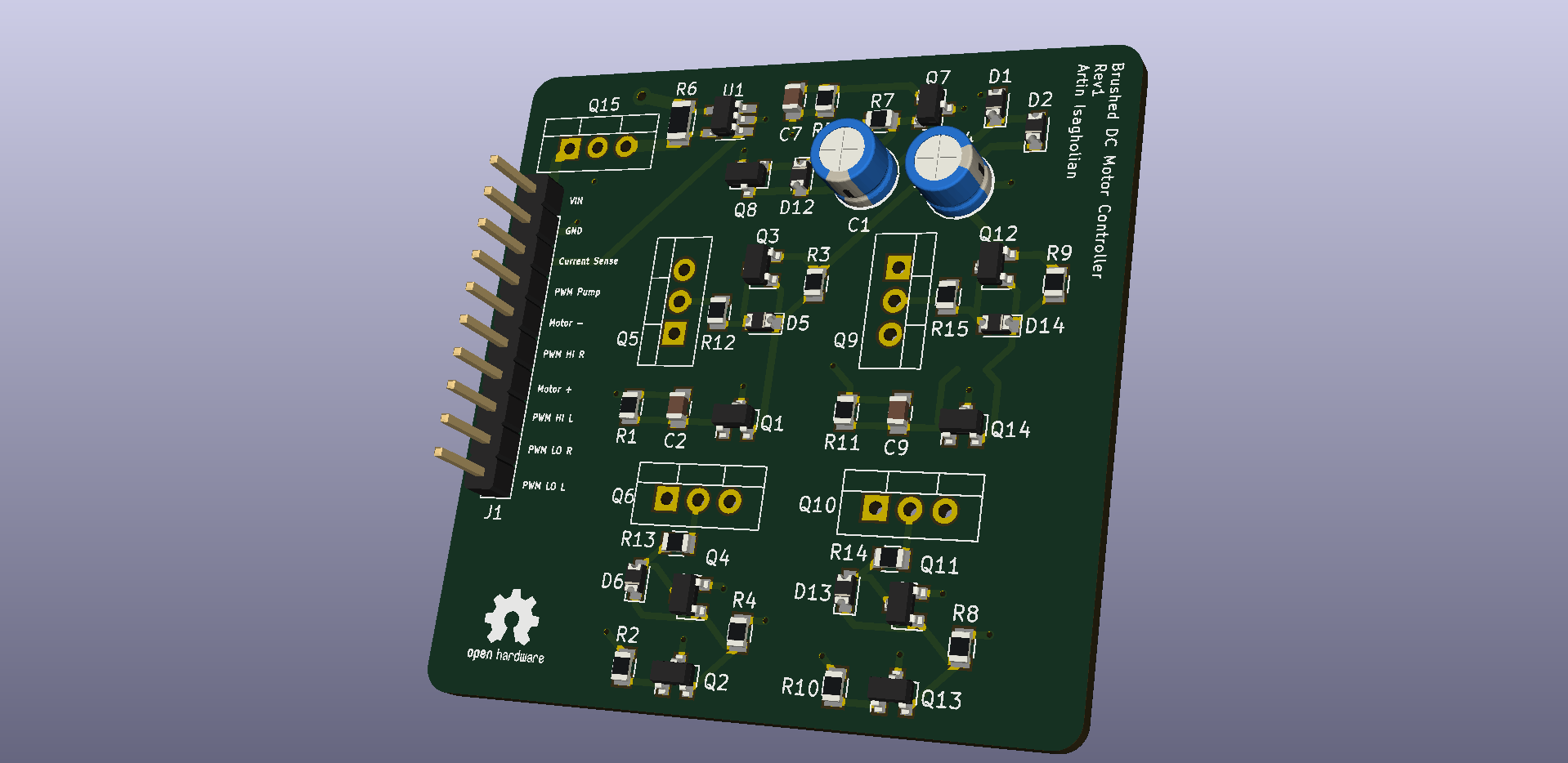
Design Overview
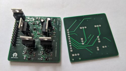
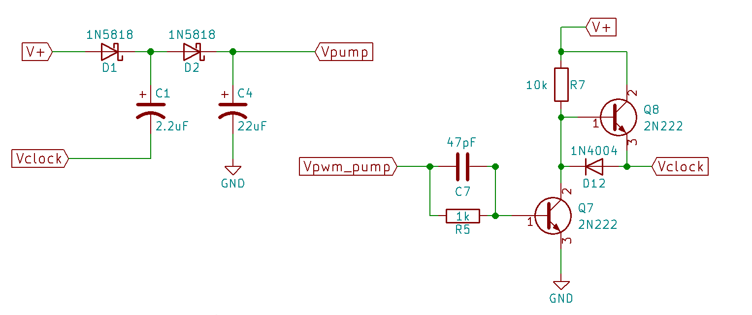
Charge Pump and Bridge
An important feature of this bridge is that all the switches are N type mosfets. N type mosfets are superior to P type fets because they have a lower Rds ON and tend to be cheaper than P type mosfets of similar performance. However, using n type fets for high side switching comes at a hidden cost. Since this design is powered by a single source (the battery) we won’t be able to drive the high side n type mosfet without a second voltage source that is at least VT greater than the battery source. To overcome this problem, a voltage doubling Dickson charge pump is used to supply the needed voltage. More about this charge pump design can be found here.
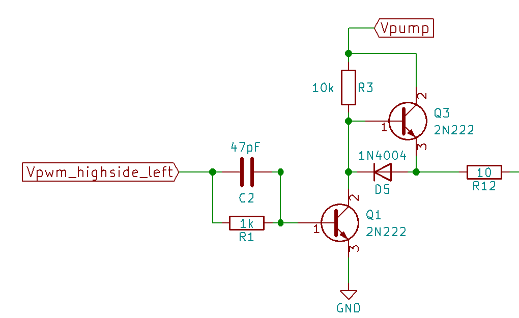
Gate Driver
Using mosfets as the switches comes with some baggage. It's a common misconception that switching a mosfet on or off comes at no cost but that is not true. The cost of turning a mosfet on or off is the amount of energy it takes to deliver/remove enough charge to fill the gate and other parasitic capacitances of the mosfet. This means the quicker we want to turn a mosfet on or off, the more current we must be able to deliver/sink to or form the gate. This design uses a microcontroller to signal the switching of the hbridge's mosfets which present a few problems that necessitate the use of a gate driver.
Microcontrollers typically run at 3.3V or 5V which means they can only switch mosfets that can turn on at those voltages. Even if your design accommodates such voltages, the amount of total current a typical microcontroller can output is around 50-100mA. Driving gates with such low current will mean very slow and by extension inefficient switching. Finally, it is generally bad practice to drive the mosfets of an inverter directly from a microcontroler with out some form of isolation circuit as a fault could cause the costly destruction of your microcontroller. For these reasons this design uses the discrete gate driver pictured below to drive the gates of the hbridge with a microcontroller PWM signal as its input. For more information on gate drivers and the design of the gate driver pictured below see my article on Designing Simple Discrete Gate Driver Circuits.
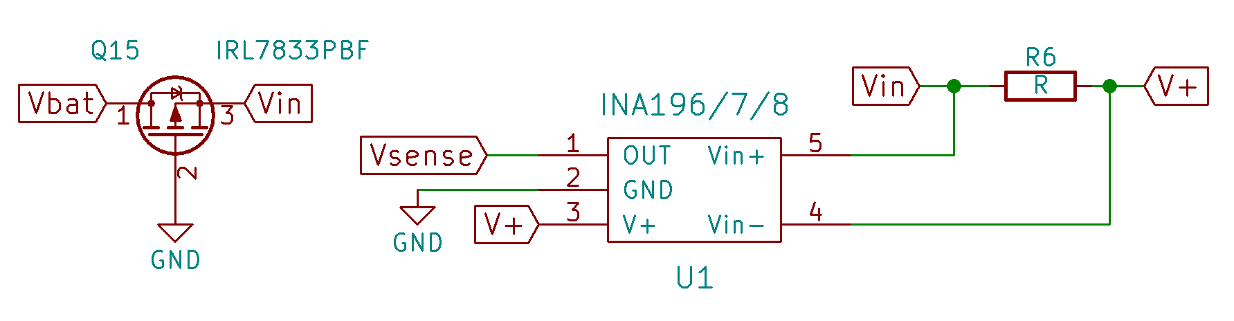
Current Sense and Reverse Polarity Protection
Knowing the amount of current that is being drawn by the bridge is crucial in detecting shoot throughs. By putting a current sense resistor in series between the battery and the hbridge we can measure the current drawn by the bridge via the voltage drop across the resistor. This voltage is probed by the INA196 current sense amplifier which amplifies the small voltage drop across the current sense resistor to a 0-5V signal that can be interpreted by the microcontroller. Using the INA196 with a current sense resistor the sense Votlage = I*Rsense*Gain. The INA196 has a gain of 20, so we choose a sense resistor, R6, that will give us adequate readings.
To give the circuit reverse polarity protection, a single PMOS transistor is used. If the user plugs in the battery backwards, the PMOS will turn off cutting off all power.
Schematic and Gerber Downloads:
Arduino Control Code
int hsl = 8; //high side left
int hsr = 9; //high side right
int lsl = 10; //low side left
int lsr = 11; //low side right
int speed = 100; //0-255
int lastcmd = 0;

void setup() {
  // initialize serial port and outputs:
  Serial.begin(96000);
  pinMode(hsl, OUTPUT);
  pinMode(hsr, OUTPUT);
  pinMode(lsl, OUTPUT);
  pinMode(lsr, OUTPUT);
}

void pause()
{
  analogWrite(hsl, 0);
  analogWrite(hsr, 0);
  analogWrite(lsl, 0);
  analogWrite(lsr, 0);
}
void forward() {
  pause(); //turn off all gates before direction changes
  analogWrite(hsl, speed);
  analogWrite(hsr, 0);
  analogWrite(lsl, 0);
  analogWrite(lsr, 255);
}

void reverse() {
  pause(); //turn off all gates before direction changes
  analogWrite(hsl, 0);
  analogWrite(hsr, speed);
  analogWrite(lsl, 255);
  analogWrite(lsr, 0);
}

void loop() {
  if (Serial.available()) {
    int inByte = Serial.read();
    if (inByte != lastcmd)
    {
      lastcmd = inByte;
      if(inByte == 'w')
      {
        Serial.write('forward');
        forward();
      }
      if(inByte =='s')
      {
        Serial.write('reverse');
        reverse();
      }
      if(inByte ==' ')
      {
        Serial.write('pause');
        pause();